Wiring A Three Way Switch Diagram, How To Wire A 3 Way Switch Wiring Diagram Dengarden Home And Garden
- How To Wire A Pilot Light Switch 2 And 3 Way Wiring
- Wiring Diagram For A Three Way Switch
- 3 Way Switches Electrical 101
- How To Wire A 3 Way Switch
- How To Wire A 3 Way Switch Wiring Diagram Dengarden Home And Garden
- Diagram Wire A 3 Way Switch Diagram Full Version Hd Quality Switch Diagram Sitexzubia Filmarco It
- Diagram Wire 3 Way Switch Diagram Wiring Full Version Hd Quality Diagram Wiring Diagramtisar Corocrozdalastria It
- Https Encrypted Tbn0 Gstatic Com Images Q Tbn And9gcr5nancjryc7jp5gewtelssmai2lwm16kfo1 Yo83bncaermxl4 Usqp Cau
- Schema Wiring Diagram For 3 Way Switch Ceiling Fan Hd Version Diagram69 Bruxelles Enscene Be
- Tiny House Electrical Understanding The 3 Way Switch
Find, Read, And Discover Wiring A Three Way Switch Diagram, Such Us:
- Diagram 3 Way Switch Wiring Diagram With 3 Lights Full Version Hd Quality 3 Lights Tsou As4a Fr
- How To Wire A Pilot Light Switch 2 And 3 Way Wiring
- 3 Way Or Three Way Switch Maintenance And Troubleshooting
- Lighting Circuit Diagrams For 1 2 And 3 Way Switching
- Diagram Wiring Diagram 4 Way Switch Diagrams Power From Full Version Hd Quality Power From Plotdiagrampdf Gianpierodalia It
If you are searching for Molecular Orbital Diagram Of Ozone you've arrived at the perfect location. We have 104 images about molecular orbital diagram of ozone adding images, pictures, photos, wallpapers, and much more. In such web page, we also provide variety of graphics out there. Such as png, jpg, animated gifs, pic art, logo, black and white, translucent, etc.

3 Way Switch Wiring Diagram Light Switch Wiring 3 Way Switch Wiring Three Way Switch Molecular Orbital Diagram Of Ozone
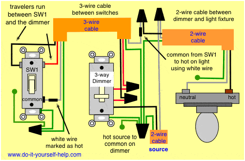
This 3 way light switch diagram shows connections when the power comes into the first switch on to the second switch and then on to two or more lights switched by the 3 way circuit.

Molecular orbital diagram of ozone. Regardless of what 3 way switch wiring diagram youre following youll need to use a 3 wire cable to connect the two 3 way light switches. Pick the diagram that is most like the scenario you are in and see if you can wire your switch. At each switch in the above 3 way switch wiring diagram the black wire gets connected to the common copper or black screw.
So what you should see if you have correct 3 wire electrical cable romex is a black power white neutral and now a 3rd red wire. In the ceiling light fixture electrical box one black wire from a 3 way switch gets connected to the black load wire on the light fixture. Wiring diagram 3 way switch with light at the end in this diagram the electrical source is at the first switch and the light is located at the end of the circuit.
The goal is to place two switches at separate locations which control the exact same device. 3 way switch wiring diagram. This might seem intimidating but it does not have to be.
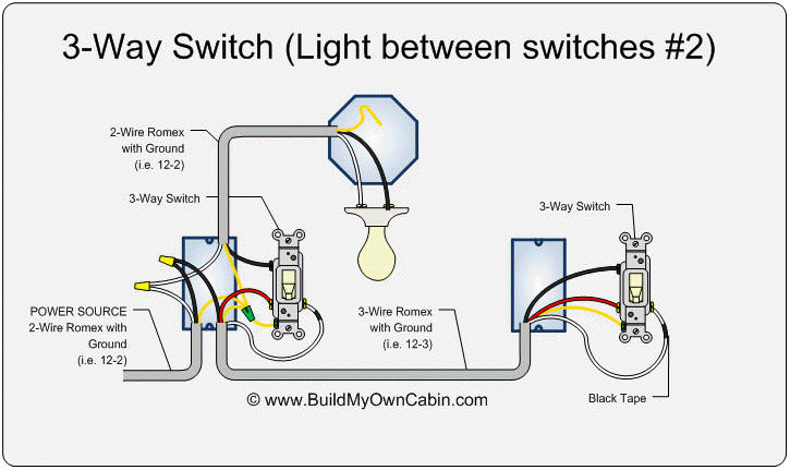
The white wire of the cable going to the switch is attached to the black line in the fixture box using a wire nut. Electrically a typical 3 way switch is a single pole double throw spdt switch. Wiring diagrams for 3 way switches 3 way switch diagram 2 above shows the electricity source starting at the fixture.
In this diagram the incoming hot wire attaches to the first switchs common dark colored terminal. Refer to the above 3 way switch diagram. 3 way switch wiring diagram depicting all wires in the ceiling junction box.
This 3 way switch wiring diagram shows how to wire the switches and the light when the power is coming to the light switch. Three wire cable runs between the switches and 2 wire cable runs to the light. In the above 3 way switch wiring diagram at each switch the black wire gets connected to the copper or black screw.
The white wire becomes the energized switch leg as indicated by using black or red electrical tape. Three way switches allow for controlling a light fixture from two separate locations these are usually used at the top and bottom of a flight of stairs or at two different entrances to a room. Run new cable romex between the 3 way switches.
With these diagrams below it will take the guess work out of wiring. Take a closer look at a 3 way switch wiring diagram. A three way switch is fundamentally different in its operation from a regular two way switch.
The two hot wires of three wire cable connect to a pair of brass colored traveler terminals on each switch. The black and red wires between sw1 and sw2 are connected to the traveler terminals. By correctly connecting two of these switches together toggling either switch changes the state of the load from off to on or vice versa.
Regardless of what 3 way switch wiring diagram youre following youll need to use a 3 wire cable to connect the two 3 way light switches. 3 way switch wiring diagram depicting all wires in the ceiling junction box.
Molecular Orbital Diagram Of Ozone, How To Wire A 3 Way Switch Wiring Diagram Dengarden Home And Garden
- 3 Way Switch Wiring Electrical 101
- Multiway Switching Wikipedia
- Two Lights Between 3 Way Switches Power Via A Switch How To Wire A Light Switch
Molecular Orbital Diagram Of Ozone, Diagram 3 Way Switch Wiring Diagram Power From Full Version Hd Quality Power From Forddiagram Biorygen It
- Https Encrypted Tbn0 Gstatic Com Images Q Tbn And9gctx2lc3wn6 Mdz C7kh6mdaczrwyhiffzuoeq1q5cftjakhbsds Usqp Cau
- The Three Way Switch
- Diagram Wire 4 Way Switch Diagram Full Version Hd Quality Switch Diagram Diagrammoosu Arborealive It
Molecular Orbital Diagram Of Ozone, How To Wire Three Way Switches Part 2
- Asihome Articles Guides Installing Three Way X10 Compatible Switches
- 3 Way Switch Wiring Electrical 101
- Swap Out Those Old Crappy 3 Way Light Switches For Good Cnet
More From Molecular Orbital Diagram Of Ozone
- Diagram Of Gametophyte Bearing A Sporophyte
- What Is Transition Diagram
- Mips Block Diagram
- Electron Dot Symbol For Carbon
- Creately Flowchart
Incoming Search Terms:
- 6d078 Diagram Of Wiring A 3 Way Switch Wiring Library Creately Flowchart,
- How To Wire A 3 Way Switch Wiring Diagram Dengarden Home And Garden Creately Flowchart,
- Diagram Wire 3 Way Switch Diagram Wiring Full Version Hd Quality Diagram Wiring Diagramtisar Corocrozdalastria It Creately Flowchart,
- How To Wire A Three Way Switch Diagram Tutorial Lighting Electric Hut Creately Flowchart,
- Combination Light Switch Wiring Diagram Enotecaombrerosse It Creately Flowchart,
- 3 Way Diagrams For Zen21 Zen22 Zen23 And Zen24 Switches Zooz Support Center Creately Flowchart,


