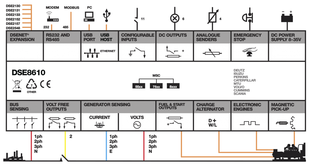
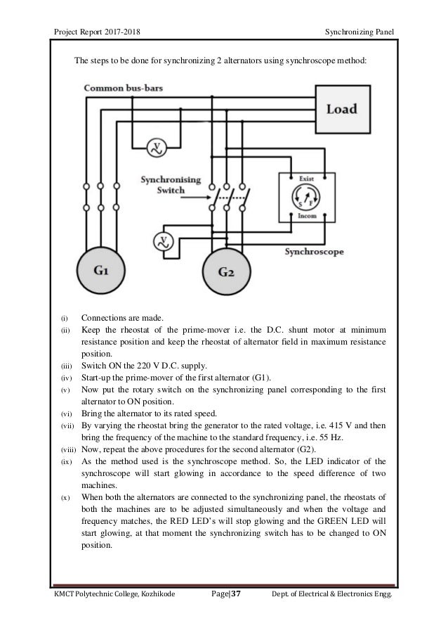
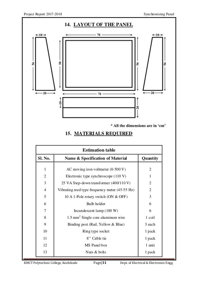
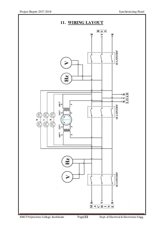
Synchronizing Panel Circuit Diagram, Schematic Diagram Of The Three Substation Power System Download Scientific Diagram
- Https Arxiv Org Pdf 1907 00339
- 2 A Concept For Standardized Electrical Control Systems
- Wiring For Alternators
- How To Synchronize Generators On A Ship
- Https Www Irjet Net Archives V2 I4 Irjet V2i4299 Pdf
- Synchronization Board Diagram For Generator Electrical Wiring Diagram Generation Power
- Deepsea Sync Panel Youtube
- How To Work With The Speed Controller Of The Diesel Generator Set
- 10 Synchronization Panel Ideas Paneling Generation Tower Light
- Belajar Komponen Panel Listrik Lengkap 2019
Find, Read, And Discover Synchronizing Panel Circuit Diagram, Such Us:
- Genset Synchronizing Panel Wiring Diagram 02 Yamaha R1 Fuse Box Location 1982dodge Ke2x Jeanjaures37 Fr
- Synchronizing Panel 3d Cad Model Library Grabcad
- Synchronization Board Diagram For Generator Electrical Wiring Diagram Generation Power
- Wiring For Alternators
- 4c49d Generator Synchronizing Panel Wiring Diagram Wiring Resources
If you are looking for Use Of Venn Diagram you've come to the perfect location. We have 104 images about use of venn diagram including images, pictures, photos, backgrounds, and more. In such page, we also provide number of images available. Such as png, jpg, animated gifs, pic art, symbol, blackandwhite, translucent, etc.
To a 41116 41116 218 back box and shall control two styley class b or one style z class a circuit.

Use of venn diagram. Basics 10 480 v pump schematic. Simple led circuits led projects schematic circuit diagram may 26 2020. Basics 13 valve limit switch legend.
This is a start stop push button control schematic which includes contactor m overload relay control transformer and push buttons. Basics 11 mov schematic with block included basics 12 12 208 vac panel diagram. Voltage monitoring circuit for 12 volt lipo battery pack schematic circuit diagram may 25 2020.
Voltage monitoring circuit for 12 volt lipo battery pack schematic circuit diagram may 25 2020. 3 shows the block diagram and fig. Voltage synchronization a voltage control loop design.
Basics 14 aov schematic with block included basics 15 wiring or connection. Basics 7 416 kv 3 line diagram. Synchronizing panel works between two or more different power sources like dg sets to manage power supply.
The output voltage. Synchronizing a distributed generator dg to the power grid. 950mhz 2000mhz analog satellite finder schematic circuit diagram may 28 2020.
4 shows the front panel window in labview of speed control loop. Synchronization helps in making different dg sets behave as a virtual single unit and eliminates subdivision of total load. If the phase sequence is incorrect no such instant will take place and all the lamps will be dark simultaneously.
Synchronizing transistors schematic circuit diagram may 27 2020. The contactor contains large load contacts that are intend to handle large amount of current. The synchronizing panel includes indications of voltage angle and slip that show what adjustments the operator needs to make to the governor and exciter and when it is acceptable for the operator to close the breaker.
The diagram is shown below. Basics 9 416 kv pump schematic. Figure1 a the per phase equivalent circuit of a synchronous generator without armature reaction while depicting the revolving field produced by the rotor.
Simple led circuits led projects schematic circuit diagram may 26 2020. In many cases the process is automated using an automatic synchronizer with manual control available as a. The phasor diagrams for a b lagging pf c unity pf and d leading pf.
Basics 8 aov elementary block diagram. Synchronizing transistors schematic circuit diagram may 27 2020. The module shall be capable of multiple zone synchronization by connecting multiple modules slaves together.
The feeder pillar panels are used to terminate and distribute the control circuits. The wiring diagram for connecting thee phase motor to the supply along with control wiring is shown in figure below. Slaves can be driven bfrom either the slave output of a prior mdl3 or from the nac output of the master.
Use Of Venn Diagram, Diagram Proton Wira Wiring Diagram Full Version Hd Quality Wiring Diagram Oilschematics1j Romaindanza It
- Synchronizing
- Spreadsheet To Calculate Short Circuit Capacity Of Diesel Generator Synchronizing Panel
- Transfer Switch Wikipedia
Use Of Venn Diagram, Schematic Diagram Of The Three Substation Power System Download Scientific Diagram
- Syncronizing Load Sharing Controls
- Alternator Ac Generator Synchronizing Panel
- Design Your Control Panel And Make Wiring Diagrams By Tecogrp
Use Of Venn Diagram, Diagram Diesel Generator Synchronization Design Diagram Full Version Hd Quality Design Diagram Blogxwyss Cuartetango It
- Dg Panel Wiring Diagram 1972 C10 Headlight Wiring Diagram Bege Wiring Diagram
- Generator Synchronization Panels Eamfco
- Diagram In Pictures Database Genset Synchronizing Panel Wiring Diagram Just Download Or Read Wiring Diagram Alain Claude Sulzer Kripke Models Onyxum Com
More From Use Of Venn Diagram
- What Is A Flow Diagram In Science
- Haploid And Diploid Venn Diagram
- Tube Light Connection With Capacitor
- Schematic Diagram Of Series Circuit
- What Is The Lewis Structure For So2
Incoming Search Terms:
- Pdf Design Of An Automatic Synchronizing Device For Dual Electrical Generators Based On Can Protocol Semantic Scholar What Is The Lewis Structure For So2,
- Xo5vek9o Eycm What Is The Lewis Structure For So2,
- 10 Synchronization Panel Ideas Paneling Generation Tower Light What Is The Lewis Structure For So2,
- Diagram In Pictures Database Genset Synchronizing Panel Wiring Diagram Just Download Or Read Wiring Diagram Alain Claude Sulzer Kripke Models Onyxum Com What Is The Lewis Structure For So2,
- 1 Fundamental Principles Of Electrical Control Systems What Is The Lewis Structure For So2,
- Diagram Diesel Generator Synchronization Design Diagram Full Version Hd Quality Design Diagram Blogxwyss Cuartetango It What Is The Lewis Structure For So2,


