Motor Diagram Circuit, Electricity Circuits Symbols Circuit Diagrams
- Dc Shunt Motor Construction Circuit Diagram And Its Applications
- Circuit Diagram For The Connections Of Motor Driver L293d Download Scientific Diagram
- Motor Control Circuit Wiring Instrumentation Tools
- Motor Protection Circuits Over Voltage Over Heat Over Current Homemade Circuit Projects
- Sequence Control For Industrial Motors
- Circuit Diagram For Speed Control Of Dc Motor By Using Pwm Technique Eceprojects
- Types Of Single Phase Induction Motors Single Phase Induction Motor Wiring Diagram Electrical Academia
- Model Diagram Of Synchronous Motor Electrical4u
- Electrical Wiring Diagram Forward Reverse Motor Control And Power Circuit Using Mitsubishi Plc Technovation Technological Innovation And Advanced Industrial Control Technologies
- Offline Copies Of Chapter Quizzes Basic Motor Control
Find, Read, And Discover Motor Diagram Circuit, Such Us:
- Star Delta Starter Electrical Notes Articles
- Circuit Diagram Of Time Delay Of Starting Three Motors
- Dc Shunt Motor Construction Circuit Diagram And Its Applications
- On Off Electric Motor Control Circuits Discrete Control System Elements Automation Textbook
- Circuit Diagram For The Connections Of Motor Driver L293d Download Scientific Diagram
If you are searching for Draw And Label The Parts Of Circulatory System you've reached the ideal location. We ve got 104 images about draw and label the parts of circulatory system including images, pictures, photos, backgrounds, and much more. In such webpage, we also have number of graphics available. Such as png, jpg, animated gifs, pic art, logo, blackandwhite, transparent, etc.
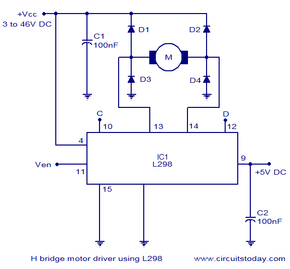
H Bridge Motor Control Circuit Schematic Diagram Using Ic L298 Draw And Label The Parts Of Circulatory System

Arduino Motor Control Explained In Detail Draw And Label The Parts Of Circulatory System
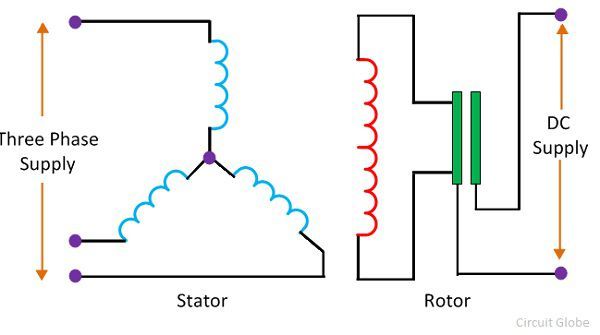
Working Principle Of A Synchronous Motor Circuit Globe Draw And Label The Parts Of Circulatory System

Interpretation And Application Of Simple Wiring And Elementary Diagrams Draw And Label The Parts Of Circulatory System

Offline Copies Of Chapter Quizzes Basic Motor Control Draw And Label The Parts Of Circulatory System

Dc Motor Speed Controller Circuit Draw And Label The Parts Of Circulatory System
What is stepper motor driver.
Draw and label the parts of circulatory system. In a series motor electric power is supplied between one end of the series field windings and one end of the armature. Also explain the operation of this motor control circuit. When voltage is applied current flows from power supply terminals through the series winding and armature winding.
Now as shown in the circuit diagram the 555 circuit here is to generate clock or the square wave. The figure shows the circuit diagram of two stage stepper motor driver. The interlock contacts installed in the previous sections motor control circuit work fine as discussed in previous article but the motor will run only as long as each pushbutton switch is held down.
Refer to the motor manufacturers data on the motor for wiring diagrams on standard frame ex e ex d etc. Inst maint wiringqxd 5032008 1002 am page 6. These diagrams are current at the time of publication check the wiring diagram supplied with the motor.
Line diagrams also called schematic or elementary diagrams show the circuits which form the basic operation of the controller. Three phase motor power control wiring diagrams three phase motor connection schematic power and control wiring installation diagrams. They do not indicate the physical relationships of the various components in the controller.
They are an ideal means for troubleshooting a circuit. It is often called a stepper motor driver. The stator circuit model of an induction motor consists of a stator phase winding resistance r 1 stator phase winding leakage reactance x 1 as shown in the circuit diagram below.
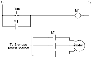
The frequency of clock generation in this case cannot be kept constant so we need to get variable speed for the stepper motor. Continuous motor operation with a momentary start switch is possible if a normally open seal in contact from the contactor is connected in parallel with the start switch so that once the contactor is energized it. A stepper motor driver or stepper motor drive is a circuit which is used to drive or run a stepper motor.
Line diagrams show circuits of the operation of the controller. Dc series motor circuit diagram. Already we discussed about the basics of permissive and interlock circuits in previous post also discussed about the basic motor control logic using forward reverse control.
Motor contactor or starter coils are typically designated by the letter m in ladder logic diagrams. Stepper motor driver circuit diagram and explanation. A stepper motor driver usually consists of a controller a.
The no load current i 0 is simulated by a pure inductive reactor x 0 taking the magnetizing component i u and a noninductive resistor r 0 carrying the core loss current i w. Star delta y d 3 phase motor starting method by automatic star delta starter with timer.

Inching Control Circuit Diagram Page 1 Line 17qq Com Draw And Label The Parts Of Circulatory System

Dc Motor Direction Control Using Relay Circuit Draw And Label The Parts Of Circulatory System
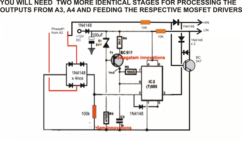
Driving 3 Phase Motor On Single Phase Supply Homemade Circuit Projects Draw And Label The Parts Of Circulatory System
Ac Motor Control Circuits Worksheet Ac Electric Circuits Draw And Label The Parts Of Circulatory System
Draw And Label The Parts Of Circulatory System, Using Star Delta Motor Control With Circuit Diagrams Turbofuture Technology
- Circuit Diagram Of Motor Controller Download Scientific Diagram
- Arduino Motor Control Explained In Detail
- Https Encrypted Tbn0 Gstatic Com Images Q Tbn And9gcqq1sezm B7xt7strjd4whi Sh7dbjwttnaeiywyhjaifx Ldma Usqp Cau
Draw And Label The Parts Of Circulatory System, Star Delta Starter Explained In Plain English Electrical4u
- Dc Motor Servo Circuit Composed Of Ma741 Basic Circuit Circuit Diagram Seekic Com
- Control Tutorials For Matlab And Simulink Motor Speed System Modeling
- Ac Motor Control Circuits Worksheet Ac Electric Circuits
Draw And Label The Parts Of Circulatory System, 5 Contactor Circuits
- Ac Motor Control Circuits Worksheet Ac Electric Circuits
- Characteristic Of A Dc Series Motor My Tech Info
- Https Encrypted Tbn0 Gstatic Com Images Q Tbn And9gctwjay6zjkwgqn4ecucpulztrqjeauaw9j1aonki3exfiafqc9j Usqp Cau
More From Draw And Label The Parts Of Circulatory System
- Schematic Diagram Maker
- Diagram Of Change Of State Of Matter
- Lithium Atom Drawing
- Molecular Orbital Theory Pdf
- Visio Tree Diagram
Incoming Search Terms:
- Control Tutorials For Matlab And Simulink Motor Speed System Modeling Visio Tree Diagram,
- Motor Control Circuits Types Electrical Industrial Automation Plc Programming Scada Pid Control System Visio Tree Diagram,
- Motor Control Circuit Diagram Start Stop 3 Wire Control Youtube Visio Tree Diagram,
- Ac Motor Control Circuits Worksheet Ac Electric Circuits Visio Tree Diagram,
- Application Circuit Of Tpd4207f For Small Compressor Motor Drive Toshiba Electronic Devices Storage Corporation Asia English Visio Tree Diagram,
- 3 Visio Tree Diagram,