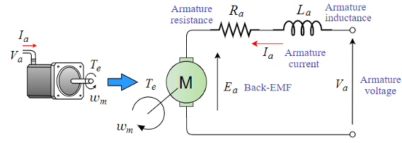
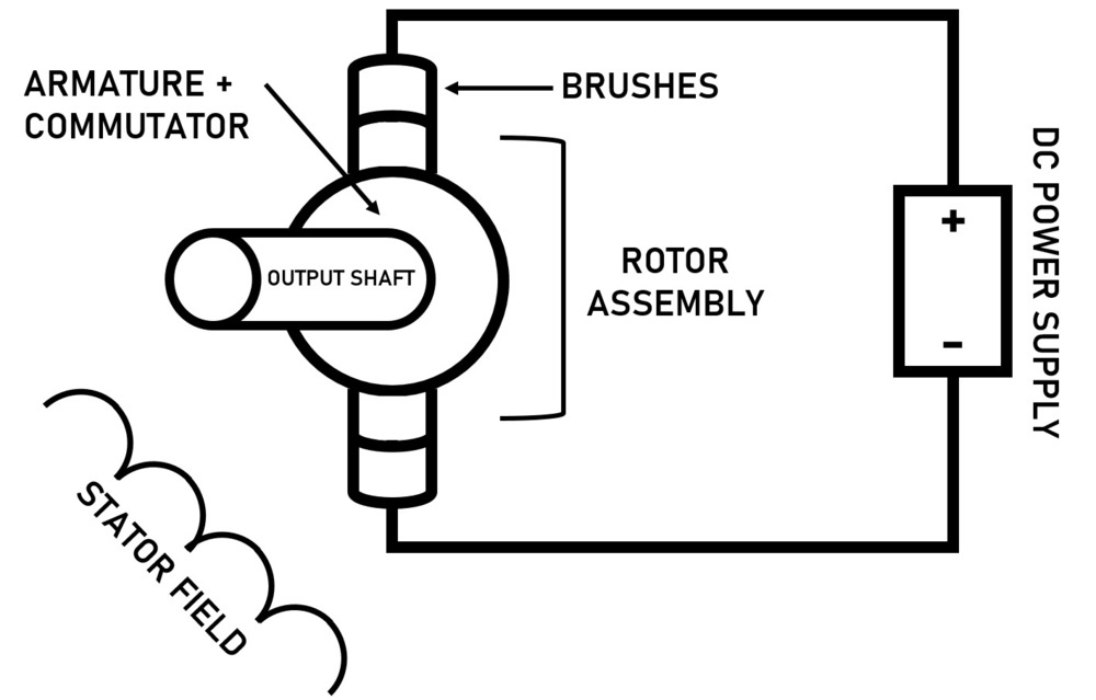
Motor Diagram Armature, Dc Motor Types Brushed Brushless And Dc Servo Motor
- Dc Motor Connections Instrumentation Tools
- Speed Control Methods Of Dc Motor Electricaleasy Com
- Basic Construction And Working Of A Dc Generator Electricaleasy Com
- Armature Resistance Control Of Dc Motor Rheostatic Speed Control Of Dc Motor Electrical Diary Diary Of Electrical Engineer
- Dc Motor Armature Winding Question Physics Forums
- Solved 3 Another Way To Control A De Motor Is To Keep Th Chegg Com
- Dc Motors Explained Advantages Of Brushed Brushless Motors Youtube
- How Does Torque Vary With Armature Current In Dc Series Motor Quora
- Dc Motor Construction Parts
- Dc Motor Armature Winding Circuit Diagram Electrical Equipment Circuit Circuit Diagram Seekic Com
Find, Read, And Discover Motor Diagram Armature, Such Us:
- Construction Of Dc Motor Your Electrical Guide
- Dc Motor Model With Electrical And Torque Characteristics And Fault Modeling Simulink Mathworks America Latina
- Types Of Dc Motor Steadt State Equivalent Circuit Moving Coil Motors
- Working Or Operating Principle Of Dc Motor Electrical4u
- Https Encrypted Tbn0 Gstatic Com Images Q Tbn And9gcre6y8jqwueh6aaevmelwpoj6eag Euotpxksa0jk1e 35yqzh4 Usqp Cau
If you re looking for Molecular Orbital Theory Of F2 you've come to the perfect place. We have 103 graphics about molecular orbital theory of f2 adding images, photos, pictures, backgrounds, and more. In these webpage, we also provide number of graphics out there. Such as png, jpg, animated gifs, pic art, logo, blackandwhite, translucent, etc.

Block Diagram Of An Armature Controlled Dc Motor Download Scientific Diagram Molecular Orbital Theory Of F2
Https Encrypted Tbn0 Gstatic Com Images Q Tbn And9gcsbumjtiqxp3djksqfxgj8p1i7t Zpdb3wym0 Nvn7i06jjnrn Usqp Cau Molecular Orbital Theory Of F2
In the split series three wire reversible type universal motor one stator coil is used to obtain one direction and the other stator coil to obtain the other direction with only one stator coil being in the circuit at a.

Molecular orbital theory of f2. Front side and end on. The armature conducts ac even on dc direct current machines via the commutator which periodically reverses current direction or due to electronic commutation eg. In the diagram to the right you can see three different views of the same armature.
This winding is placed in the slots of a rotor whereas the field winding is placed in slots of the stator. After reading this topic armature controlled dc servomotor in the control system you will understand the theory derivation expressions transfer function and block diagram. Armature resistance control of dc motor.
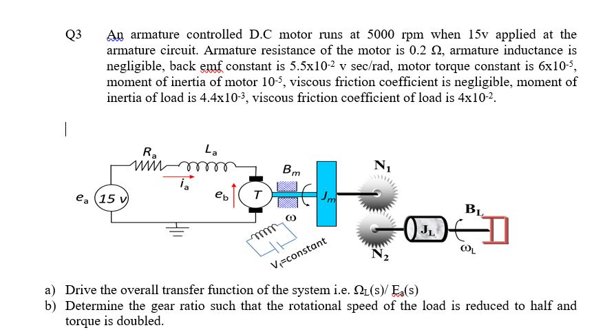
In this method a variable resistor r e is put in the armature circuit. Consider the armature controlled dc motor and assume that the demagnetizing effect of armature reaction is neglected magnetic circuit is assumed linear and field voltage is constant ie. The electrical system consists of the armature and the field circuit but for analysis purpose only the armature circuit is considered because the field is excited by a constant voltagethe mechanical system consist of the rotating part of the motor and load connected to the shaft of the motorthe armature controlled dc motor speed control system is shown in the below figure.
The armature is an electromagnet made by coiling thin wire around two or more poles of a metal core. What is an armature. The armature has an axle and the commutator is attached to the axle.
The variation in the variable resistance does not affect the flux as the field is directly connected to the supply mains. The armature windings conduct ac even on dc machines due to the commutator action which periodically reverses current direction or due to electronic commutation as in brushless dc motorsthe armature can be on either the rotor rotating part or the stator stationary part. Generally this is housed on stator slots and field winding on rotor slots to machine synchronous.
The armature winding of dc motor is attached to the rotor or the rotating part of the machine and as a result is subjected to altering magnetic field in the path of its rotation which directly results in magnetic losses. The dc motor armature winding diagram is shown below. In electrical engineering an armature is the component of an electric machine which carries alternating current.
Let us consider the armature controlled dc servomotor as shown in figure 1. Block diagram and transfer function of dc motor armature controlled dc motor. Reversal of this motor is accomplished by an interchange of the brush holder leads with the armature connected off neutral.
The armature takes the place of the nail in an electric motor. An armature is defined as the component of the electric machine ie. In a brushless dc motorthe armature provides housing and support to the.
A motor or generator that carries alternating current ac.
Molecular Orbital Theory Of F2, Speed Control Of Dc Motor By Armature Resistance Control Virtual Lab Electrical Machine Experiment Youtube
- Schematic Diagram Of Armature Controlled Dc Motor Notations R Download Scientific Diagram
- Introduction To Dc Motor Basics For Beginners Electronics For You
- The Electric Equivalent Circuit Of The Armature And The Free Body Download Scientific Diagram
Molecular Orbital Theory Of F2, Dc Motor Construction Parts
- Solved 3 Another Way To Control A De Motor Is To Keep Th Chegg Com
- What Is An Armature In An Electric Motor Generator Electrical4u
- Dc Motor Speed Control Variable Speed Motor Controls And Drives Automation Textbook
Molecular Orbital Theory Of F2, Dc Motor Armature Winding Circuit Diagram Electrical Equipment Circuit Circuit Diagram Seekic Com
- Electric Traction Control The Railway Technical Website Prc Rail Consulting Ltd
- Exp 1 Transfer Function Of Armature Controlled Dc Motor Electric Motor Torque
- Solved An Armature Circuit Diagram For A Dc Motor Is Show Chegg Com
More From Molecular Orbital Theory Of F2
- Electron Dot Notation Definition
- Communication Tree Diagram
- Schematic Diagram Of Autotransformer Starter
- 2011 Vw Jetta Fuse Diagram
- What Is Flowchart In C Programming
Incoming Search Terms:
- Dc Motors General Principles Of Operation Motors And Drives What Is Flowchart In C Programming,
- Speed Control Of Dc Motor By Armature Resistance Control Virtual Lab Electrical Machine Experiment Youtube What Is Flowchart In C Programming,
- Dc Motor Types Brushed Brushless And Dc Servo Motor What Is Flowchart In C Programming,
- Armature Voltage An Overview Sciencedirect Topics What Is Flowchart In C Programming,
- Universal Motor Wikipedia What Is Flowchart In C Programming,
- How To Check A Motor Armature For Damaged Windings Groschopp What Is Flowchart In C Programming,


