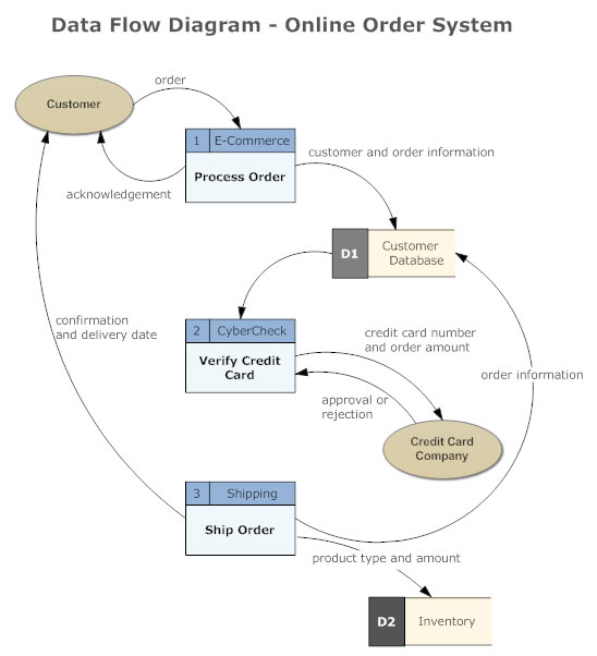
Context Diagram Software Engineering, Http Airccse Org Journal Ijsea Papers 1010ijsea6 Pdf
- Analysis Diagrams University It
- Data Flow Diagram Template Dfd Yourdon And Coad Notation Template Dfd Gane Sarson Notation Template Dfd Template
- Level 0 Dfd Context Dfd Software Engineering
- Uml Replacement For Context Diagram Stack Overflow
- Hatley Pirbhai Modeling Wikipedia
- Data Flow Diagram Software Free Dfd Templates Try Smartdraw
- Data Flow Diagram Study Guides Projects Research For Software Engineering
- Ece 355 Software Engineering Ppt Video Online Download
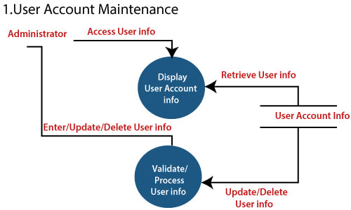
- Software Engineering Data Flow Diagrams Javatpoint
- How To Make A Data Flow Diagram Dfd Edraw Max
Find, Read, And Discover Context Diagram Software Engineering, Such Us:
- Data Flow Diagram Study Guides Projects Research For Software Engineering
- Data Flow Diagram Comprehensive Guide With Examples By Warren Lynch Medium
- System Context Diagram Wikipedia
- System Context Diagram Wikipedia
- Context Diagram Software Lucidchart
If you are searching for On The Sidewalk Bleeding Plot Diagram you've reached the perfect location. We have 104 images about on the sidewalk bleeding plot diagram including pictures, photos, photographs, backgrounds, and much more. In these webpage, we also have number of images out there. Such as png, jpg, animated gifs, pic art, symbol, black and white, translucent, etc.
This diagram is a high level view of a system.

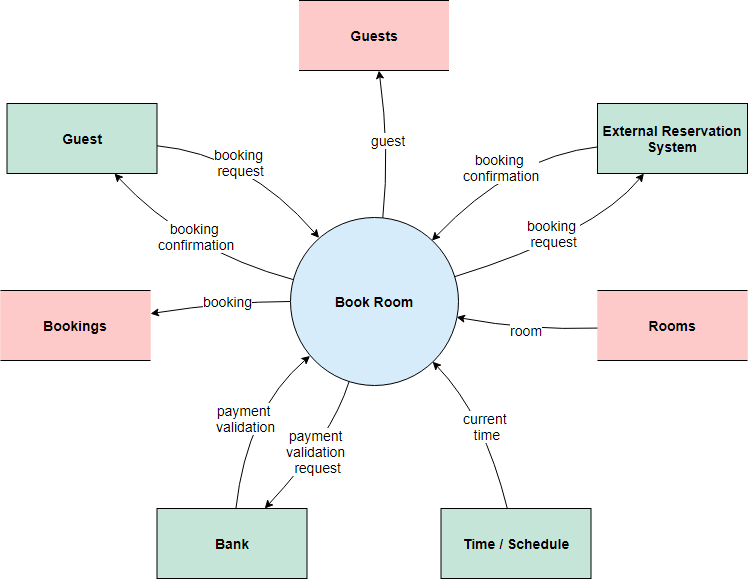
On the sidewalk bleeding plot diagram. The context diagram shows the system under consideration as a single high level process and then shows the relationship that the system has with other external entities systems organizational groups external data stores etc. It is similar to a block diagram. A system context diagram scd in software engineering and systems engineering is a diagram that defines the boundary between the system or part of a system and its environment showing the entities that interact with it.
The context diagram graphically illustrates this boundary by showing the connections between the system being developed or the problem being addressed and the outside world. Another name for a context diagram is a context level data flow diagram or a level 0 data flow diagram. It is also known as fundamental system model or context diagram represents the entire software requirement as a single bubble with input and output data denoted by incoming and outgoing arrows.
A system context diagram scd in engineering is a diagram that defines the boundary between the system or part of a system and its environment showing the entities that interact with it. The entire software system is shown as a single process. A context diagram also known as a system context diagram or level 0 dfd communicates a high level overview of the flow of data within a technical system.
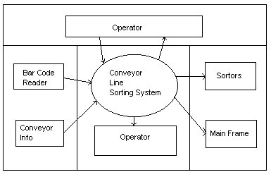
A system context diagram represents all the external components that may interact with the system hence displays the entire software system as a unit. A context diagram sometimes called a level 0 data flow diagram is drawn in order to define and clarify the boundaries of the software system. The context diagrams are widely used in software engineering and systems engineering for designing the systems that process the information.
Context diagram software to draw context diagrams online. Data flow diagram examples data flow diagrams dfds are effective to reveal relationships among the various components in a program or system. It identifies the flows of information between the system and external entities.
With virtually no technical knowledge required to understand this type of system diagram engineers analysts developers and stakeholders can easily use it as a visual reference for systems analysis and design. It is similar to a block diagram. This diagram is a high level view of a system.
The context diagram identifies the entities outside the system that interface to it in some way called terminators or external entities as well as the flow of data and material between each external entity and the system. This type of chart puts the system in the middle and surrounds it with its external parts associated entities and surroundings.
On The Sidewalk Bleeding Plot Diagram, Context Diagram Google Search Business Analysis Context Business Analyst
- The C4 Model For Visualising Software Architecture
- System Context Diagram Wikipedia
- Software Engineering And Web Designing Sample Document Flow Diagram Context Diagram And Level 1 Dfd Data Flow Diagram Of Course Management System Educational Institute
On The Sidewalk Bleeding Plot Diagram, What Is A Context Diagram Explain With Examples
- 2
- What Is Context Diagram Quora
- Online Data Flow Diagram Maker
On The Sidewalk Bleeding Plot Diagram, Data Flow Diagram Comprehensive Guide With Examples By Warren Lynch Medium
- System Context Diagram Wikipedia
- Formalization Of The Data Flow Diagram Rules For Consistency Check By International Journal Of Software Engineering Applications Ijsea Era Indexed Issuu
- Data Flow Diagram Everything You Need To Know About Dfd
More From On The Sidewalk Bleeding Plot Diagram
- Power Supply Block Diagram And Function
- Blog Diagram
- Information System Context Diagram
- Flow Chart Of Heart
- Muscle Diagram Labeled
Incoming Search Terms:
- Context Diagram An Overview Sciencedirect Topics Muscle Diagram Labeled,
- Provides A Context Diagram For The Domain Analysis Process Proposed By Download Scientific Diagram Muscle Diagram Labeled,
- 1 Real Time Requirements Intro To Software Engineering Software Development Process Models Formal Methods In Software Specification Structured Ppt Download Muscle Diagram Labeled,
- Context Diagram An Overview Sciencedirect Topics Muscle Diagram Labeled,
- What Is System Context Diagram Muscle Diagram Labeled,
- Solved Draw A Context Diagram And A Diagram 0 Dfd That Represe Chegg Com Muscle Diagram Labeled,
