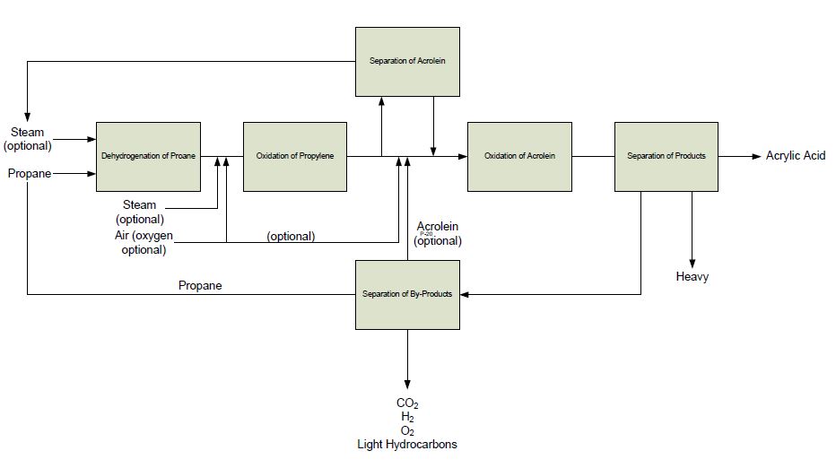
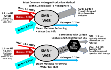
Block Flow Diagram Of Ammonia Plant, Https Encrypted Tbn0 Gstatic Com Images Q Tbn And9gctw Ytwq1x2mcz1 5aoqukagf2x 6hr9isxsz0hae3huthx4vjd Usqp Cau
- Https Ieaghg Org Exco Docs 2017 03 Pdf
- Https Encrypted Tbn0 Gstatic Com Images Q Tbn And9gctfdf J0zan Y8vkkcakafl7 Vojs4z28evv57bfml3opuhwuxu Usqp Cau
- Urea Production
- Https Encrypted Tbn0 Gstatic Com Images Q Tbn And9gct0pwisxasraasttzeeidwjel1iksq1t30uw7yj7 Gdp8hefoz0 Usqp Cau
- 3 Block Flow Diagram For Recovery Of High Purity Grade Co2 From Download Scientific Diagram
- Figure 2 1 From Optimisation Of An Ammonia Synthesis Loop Investigation Of A Novel Approach For Optimisation Of Integrated Plants Semantic Scholar
- Hno3 Manufacturing With Process Flow Diagram
- Block Diagram Ammonia Urea Plant Ureaknowhow Com Where The Urea Industry Meets
- Process Flow Diagram For The Ammonia Plant Download Scientific Diagram
- Ammonia Production Wikipedia
Find, Read, And Discover Block Flow Diagram Of Ammonia Plant, Such Us:
- Block Diagram Of Ammonia Plant Download Scientific Diagram
- Block Flow Diagram Of Tatb Process Download Scientific Diagram
- How To Increase Ammonia Plant Capacity Picture 13 13
- Https Www Nexi Go Jp Environment Info Pdf 19 004 Eiakai Part2 Pdf
- Haber Process Ammonia Manufacturing The Engineering Concepts
If you re searching for A Well Labelled Diagram Of Plant Cell you've come to the right place. We have 104 graphics about a well labelled diagram of plant cell including pictures, pictures, photos, wallpapers, and more. In these page, we also have variety of images available. Such as png, jpg, animated gifs, pic art, symbol, blackandwhite, translucent, etc.

Process Flow Diagram For The Ammonia Plant Download Scientific Diagram A Well Labelled Diagram Of Plant Cell
Figure 1 is a flow diagram of a typical single stage ammonia system showing its basic components.

A well labelled diagram of plant cell. 1620 mtpd kellogg ammonia plant catalysts composition weight in vessel and time before replacement designed by mw. Figure 1 15 piping and instrumentation diagram. The first commercial ammonia plant based on the haber bosch process was built by basf at oppau germany.
Figure 1 14 piping and instrumentation diagram for ammonia plant co 2 removal. The material flow block diagram of ammonia plant presented above shows main inputs and products only. The plant went on stream on sept.
Kellogg the ammonia plant was commissioned in 1980 and shut down in october 2002. Today most ammonia is produced on a large scale by the haber process with capacities of up to 3300 tonnes per day. In this process n 2 and h 2 gases are allowed to react at pressures of 200 bar.
Steam generated in ammonia plant is consumed internally in process as well as to drive. 4 block diagram of process for ammonia plant 32 5 block diagram of process for urea plant 33 6 block diagram for raw material utility balance 34 7 bar chart showing project completion schedule 35. Ammonia synthesis and refrigeration unit 2.
Block flow diagram of the ammonia synthesis process. A typical modern ammonia producing plant first converts natural gas liquified petroleum gas or petroleum. The reactor contained an internal heat exchanger in addition to those shown on the schematic.
Ammonia as the base for nitric acid is an important building block in the manufacture of many chemical compounds such as cleaning fluids catalysts used in the manufacture of plastics and process. Figure 1 is a flowsheet of the first commercial ammonia plant. Lack of attention to detail block flow diagrams are commonplace in university and process flow diagrams pfds are commonly the highest level of definition of plant interconnectedness.
Figure 1 12c typical process flow diagram for the production of methyl tertiary butyl ether mtbe. Simplified block diagram of a typical 1000 td ammonia plant 4. Figure 1 12b process flow diagram feed and fuel desulfurization section.
Operation of ammonia refrigeration systems. Refer section 334 and 335 for further details on material inputsoutputs expected during the operation phase. Sean moran in an applied guide to process and plant design second edition 2019.
The plant had an original capacity of 1350 metric tons per day but has been upgraded to its current capacity of 1620 metric tons per day. Chemistry of the ammonia process 3. I have never used a block flow diagram in professional practicei often go straight to piping and instrumentation.
A Well Labelled Diagram Of Plant Cell, Plant Design I Prof Dr Hasan Farag Ppt Video Online Download
- How To Increase Ammonia Plant Capacity Picture 12 13
- Ammonia 3 Production Plants Appl Major Reference Works Wiley Online Library
- Ammonia Czuppon Major Reference Works Wiley Online Library
A Well Labelled Diagram Of Plant Cell, Processes Free Full Text Co2 Utilization Via Integration Of An Industrial Post Combustion Capture Process With A Urea Plant Process Modelling And Sensitivity Analysis Html
- Neutralizers An Overview Sciencedirect Topics
- Processes Free Full Text Co2 Utilization Via Integration Of An Industrial Post Combustion Capture Process With A Urea Plant Process Modelling And Sensitivity Analysis Html
- The Uhde Ammonia Processes Fertilizer Plants
A Well Labelled Diagram Of Plant Cell, Engineers Guide Block Diagram Of Ammonia Production And Process Description Comparision Of Different Ammonia Production Methods
- Processes Free Full Text Integrated Method Of Monitoring And Optimization Of Steam Methane Reformer Process Html
- Https Ieaghg Org Exco Docs 2017 03 Pdf
- Ammonia
More From A Well Labelled Diagram Of Plant Cell
- 4 Wire Dryer Plug Diagram
- Installation Single Phase House Wiring Diagram
- 2003 F150 Fuse Diagram
- Prokaryotic Cell Diagram Simple
- Heart And Circulation Diagram
Incoming Search Terms:
- How To Increase Ammonia Plant Capacity Picture 12 13 Heart And Circulation Diagram,
- Https Web Wpi Edu Pubs E Project Available E Project 081915 125250 Unrestricted Ammonia Paper Final Pdf Heart And Circulation Diagram,
- Hydrogen Cyanide Hcn Manufacturing Process For Hydrogen Cyanide Heart And Circulation Diagram,
- Processes Free Full Text Integrated Method Of Monitoring And Optimization Of Steam Methane Reformer Process Html Heart And Circulation Diagram,
- Process Flow Diagram Of The Methanol Plant Download Scientific Diagram Heart And Circulation Diagram,
- The Uhde Ammonia Processes Fertilizer Plants Heart And Circulation Diagram,


